Note: This essay is meant for people that already have a pretty firm understanding of aeronautical engineering. I will not go into a lot of detail explaining things that are generally known in the field.
I'm writing this essay, like I do a lot of my essays, because I couldn't find this information on the net, so I had to develop it myself, and I thought I'd make that available to everybody. By the end of this essay, I will have developed a method to calculate the theoretical maximum thrust that can be produced by a propeller for a given diameter and a given power. Note that all equations use consistent units. You will have to convert all nonconsistent units (ex: 1 HP = 550 ft-lb/s).
While working on a project designing a propeller at work, I wanted to know just how good I was doing. Efficiency is one measure of how well a propeller is performing, but it's not necessarily a good indication of how well the design is performing up to its potential. In aviation, propulsive efficiency is defined as:

where η is efficiency, T is Thrust, V is Velocity, and Pavail is Power Available, or power going into the propeller. Basically, power out divided by power in. This equation is very useful for many cases, but you should see a problem in that as your velocity goes to zero, no matter how much thrust you're producing, your efficiency goes to zero. So how do you know how good your prop is doing at low speeds or statically? Well, there's another term that can be used, Figure of Merit, which is Induced Power divided by Power Available, or how much of your power is going into accelerating the air. A Figure of Merit of 1 is the best you're ever going to do. You can't accelerate the air any more than that. So, Figure of Merit gives a pretty good indication of how well the prop is doing at any airspeed. Figure of Merit is calculated as:

where F.O.M. is Figure of Merit, T is Thrust, VA is aircraft velocity, VI is induced velocity at the propeller, and Pavail is Power Available.
Now, we'd like to turn this equation around to solve for thrust for a given Figure of Merit. The only problem is that induced velocity is a function of thrust. So, let's figure out a way to solve for induced velocity. The fluid flow analogy to F=ma is
![]()
where ρ is density, A is the propeller swept area, V is the velocity at the propeller, and ΔV is the amount that the air is accelerated by the propeller, the difference between the freestream and some point downstream of the rotor where no more acceleration takes place. It's pretty well known that at the propeller, the air has accelerated one half of what it will do downstream (VI = 1/2 ΔV). So, at the propeller, the velocity is VA + 1/2 ΔV. Substituting this into the equation above yields:
![]()
Rearranging this equation into something that can be solved using the quadratic equation yields:

Solving with the quadratic equation gives:
![ΔV = [-VA ± sqrt(VA^2 + 4*1/2*T/ρA)] / 1](graphics/aviation_theory-prop_eff-eqn_6.gif)
And remembering that VI = 1/2 ΔV:
![(3) VI = [-VA ± sqrt(VA^2 + 4*1/2*T/ρA)] / 2](graphics/aviation_theory-prop_eff-eqn_7.gif)
where the addition solution, not subtraction, gives the correct answer for most conditions at which a propeller will be operating.
Now, let's go back to equation (1), and solve for thrust

Substitute that back into equation (3):
![(5) VI = [-VA + sqrt(VA^2 + 4*1/2*1/ρA*η*Pavail / VA)] / 2](graphics/aviation_theory-prop_eff-eqn_9.gif)
Now we've got the three equations that we'll need to solve for thrust for a given figure of merit. Taking the equation for Figure of Merit (2), and solving for Power Available yields:

Substitute this into the equation for efficiency (1), and simplify to get:

Subsitute equation (5) into this to get:
![η = VA * F.O.M. / { VA + [-VA + sqrt(VA^2 + 4*1/2*1/ρA*η*Pavail / VA)] / 2 }](graphics/aviation_theory-prop_eff-eqn_12.gif)
Now, I'm sure we could go on further from here, solving for η, but that would be rather tedious, and the equation would get even messier than it already is. So, from this point, I just built myself an Excel spreadsheet, and used the Solver function to solve for η. Once you have that, it's a trivial matter to go back to equation (4) and calculate your thrust.
Static Thrust
Static Thrust is a special case, since both airspeed and efficiency will be zero. This makes the final equation above that we had derived become invalid, since the denominator will be zero. But, it is extremely easy to solve for induced velocity, and then thrust from there using the F.O.M. equation. I will leave it up to the reader to go through the derivation, but the resulting equation for thrust is:
![T = [F.O.M. * Pavail / sqrt(1/2 * 1/ρA)]^(2/3)](graphics/aviation_theory-prop_eff-eqn_13.gif)
Conclusions
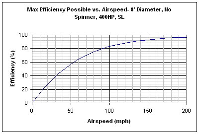
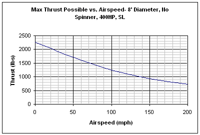
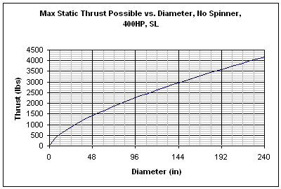
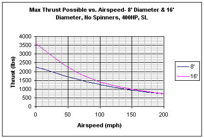
These have proven to be very useful calculations for my job when designing propellers. They show the theoretical limit of just how much thrust a propeller could be producing at any given airspeed, giving a good bench mark for my designs. These calculations can also be useful for getting a good understanding of propeller performance in general. The graphs below were made using the equations derived above. They illustrate the limitations of propellers, as well as some general trends.
In the first graph, you can clearly see that even with the propeller operating as well as it could, your efficiency is going to be lousy up until you get to a decent airspeed, but in the second graph, you can see that even with increased efficiency, your thrust drops off as airspeed increases.


The first of the next two charts shows just how important propeller diameter is to static thrust. For the same horsepower, the amount of static thrust that you can produce just keeps going up with diameter. This increased thrust won't be nearly so marked throughout the whole flight, however, as the second chart below illustrates. It can be seen that even with diameters different by a factor of 2, both propellers produced nearly the same thrust at 200 mph. Remember the equation for efficiency (1) above. It has nothing to do with diameter. The max possible efficiency is 100%, and as seen in the first graph above, once you get up to higher airspeeds, you can start approaching that efficiency even with a smaller propeller. These charts help to show why helicopters use large rotors, and modern jet engines use high bypass designs- it's a whole lot more efficient to get thrust by accelerating a large amount of air by a little bit, than to acclerate a small amount of air by a lot.

