First off, the forces acting on an airplane are usually divided into four components: lift, drag, thrust, and weight. Drag is the force pulling back on the airplane, thrust is pulling or pushing it forward. Weight is the effect of gravity pulling it towards the Earth, and lift is the force holding the airplane in the air. When an airplane is in level flight, and it is not accelerating, the lift is equal to the weight, and the thrust is equal to the drag. However, just as with any other object, if one of the forces is changed, the airplane will accelerate accordingly. For example, if the lift is increased, the airplane will climb. If the drag is increased or the thrust is decreased, the airplane will slow down.
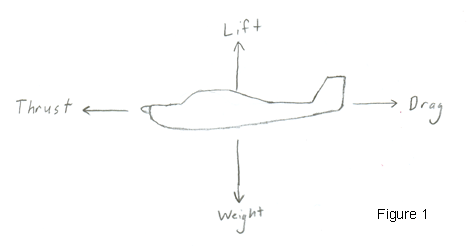
Now, what causes these forces? Weight is the force we are most familiar with. It is the force caused by the attraction between the airplane and the Earth. As an engineer and not a scientist, I don't know exactly what causes this force, I just accept it as a phenomenon that occurs in our universe.
Once an airplane is in flight, other than gravity, the only other significant way that a force can act upon the airplane is through aerodynamic means. (Other forces, such as magnetism, are so slight as to be negligible in their effects on the airplane.) One way engineers divide aerodynamic forces is to look at shear and pressure. All aerodynamic forces on an airplane can be broken down into these two components. Pressure is the force acting perpendicular to a surface, and shear is the force acting tangent or parallel to the surface. To envision this, imagine pulling a block across a level surface. The weight of the block pushing down on the surface is analagous to the pressure, and the friction is analagous to the shear. To be a bit more accurate, shear and pressure are force divided by area. So, say the block described above had an area of 1 square foot in contact with the surface, and weighed 1 pound. And assume the friction was ½ a pound. Then, the pressure would be 1 pound per square foot, and the shear would be 0.5 lbs per square foot.
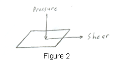
Drag is found by looking at the components of shear and pressure parallel to the direction of flight. Another way to say this is that drag is the combination of the pressure and friction with the air that holds back on an airplane.
Thrust is the force provided by the engine. In a jet engine, air is compressed into a combustion chamber. Then, heat is added by burning fuel in that chamber. The added energy causes the air to expand and accelerate out the back of the engine. The air rushing out the back of the engine provides the thrust. Propellers are another common way of providing thrust. They are used with reciprocating engines or with jet engines. Propellers also generate thrust by accelerating the air and pushing it behind them. However, propellers work by accelerating a larger amount of air to a lesser degree. Propellers accelerate the air by acting like a wing. However, instead of being fixed to the airplane and being more or less parallel to the ground, they revolve about an axis and are more or less perpendicular to the ground. You have probably seen gliders or paper airplanes that do not have engines. These do not have thrust. Therefore, they cannot maintain level flight. They are falling the whole time they fly. The only way they can stay in the air so long is by flying into updrafts, where the air itself pushes up on the airplane.
The last force to discuss is lift. Similarly to drag, lift is a combination of the shear and pressure acting on the airplane. Lift is the component of these perpendicular to the direction of flight. It is the force that keeps the airplane in the air. The part of the airplane that contributes the most to the lift is the wing. Since this is the component that contributes the most to lift, and for propeller driven aircraft, to thrust, it is important to understand how a wing works. The first thing to stress is that the normal explanation involving the shape of the wing is very misleading. Although the shape is very important, if it were the only way a wing generated lift, airplanes would not be able to fly upside down. Also, paper airplanes with their flat wings would not be able to glide. The most important aspect is that an airplane flies by pushing down on the air. The more air the wing pushes on, and the harder it pushes on it, the more lift will be created. This is the same phenomenon experienced when you put your hand out the car window at some angle. Your hand pushes down on the air, and the air pushes up on your hand. Your hand is not shaped like a typical wing, yet it still produces lift. So, why are wings shaped the way they are?
The way a wing produces lift is by deflecting air downward. To deflect the air, the wing must change the pressure of the air in order to cause an acceleration (remember that pressure is a force per area), which causes a lower pressure on top of the wing and a higher pressure on the bottom of the wing, which pushes the wing up. But no matter what the pressure distribution actually looks like, just remember that the wing must deflect the air to cause this change in pressure.
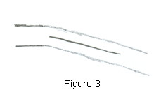
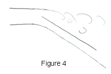
So, if one had to go about creating a wing without ever having seen one, what would that person do. I'd imagine the first thing would be to take a flat plate and mount it at an angle to the flight direction (See Figure 3). Engineers call this angle the angle of attack. This would deflect the air and create lift, but one would notice that increasing this angle past just a few degrees would cause a great loss in performance. What's happening at that angle is that the air can no longer change direction fast enough to stick to the top of the plate, so it's separating from the plate and not being deflected. This is what's known as stall (See Figure 4). The lift doesn't go away completely since the bottom surface is still deflecting some air, but it's not nearly as much lift as when the flow is still attached to the upper surface.
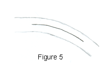
So, if you want to deflect the air more, you need a way to deflect it gradually over a distance, not all at once right at the leading edge of the plate. So, you add a bit of curve to the plate (See Figure 5). This gives the air more time to change direction, so you can deflect it more. One can imagine that the best way to do this would be to have the leading edge of the plate line up with the airflow to cause the least disturbance before trying to deflect the air. So now we have a thin curved plate as our wing, attached to the airplane at some angle that the leading edge of the plate lines up with the oncoming air. Now, what happens if we speed up or slow down, and change the angle of the airplane. The leading edge no longer lines up with the oncoming air, and once again we get a stall, decreasing the performance of the wing.
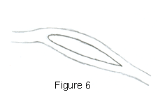
So we need a way to ensure that the leading edge always lines up with the oncoming air. This is accomplished by adding thickness to the wing to enable making the leading edge a curve (See Figure 6). Now, no matter what angle the wing is at, the air can flow smoothly over the leading edge. And now we have a typical wing. It's curved, with a round leading edge and some thickness. If we need to change the lift being made, we can change the angle of the wing relative to the airflow. Also, since lift is dependent on the amount of air being deflected, if we speed up or slow down, we're affecting the amount of air going past the wing, so that also changes the lift. When pilots change speed, they compensate for that effect by changing the angle of the wing (by changing the angle of the whole airplane) to keep the lift constant.
Notice that although the shape of a wing is very important in creating the lift, the angle of attack also plays a very important role. An airplane can fly upside down, it's just that it needs to be at a higher angle of attack to compensate for the curve of the wing. Also, a wing can be symmetrical on the top and bottom (many aerobatic planes actually do have symmetrical wings). The curve on the top surface is still important, as it allows the air to change direction gradually, but the average curve of the wing is zero.
For some actual photos of airflow over a wing, look at the Wind Tunnel Testing section of my page devoted to the University of Maryland's Heavy Lift aircraft for 2001. The main purpose of these tests was to measure lift and drag, but the smoke visualization provided a graphic way to understand the flow, and where the drag was coming from.
I hope this article is helpful. Let me know if you have any questions.
Number of visitors since 16 January, 2002: